LightWave is regarded by many people as the Amiga's premier 3D rendering system. The following is a comprehensive guide to its functions and operation. You could call it a 'plain English' rewrite of the rather quirky manual provided with the NewTek package. The information contained here is applicable to LightWave running on different platforms, though it was prepared using version 3.5 on the Amiga. Subsequent versions have expanded capability and some additional features, like Inverse Kinematics, MetaNURBS and Plug-ins, which are not included in this account. These features may be incorporated into WaveGuide at a later date. You must also understand that there is considerably more to the art of 3D modelling and animation than I can describe here. This guide concentrates on the operation of LightWave's interfaces, known as Layout and Modeler. You may have already discovered that using Modeler with competence is almost impossible without an easily understood guide. On the other hand, most people will find Layout easier to work with because its functions are pretty well self-evident. Information on both Layout and Modeler is given here in sufficient detail to enable their full potential to be explored and eventually mastered. You will also find 'Crash Course' notes to help you to dive straight into this superb piece of software. They will help you to get quickly under the skin of the programme. They should, for example, enable you to produce animated three-dimensional text, plus lens flares, in no time at all.
While NewTek's original manual is comprehensive to a fault, parts of it are poorly compiled and contain blatant errors, though others are less obvious. Also, American phraseology may be an acquired taste, but I find some of the explanations used in the manual are quite confusing. I hope this effort is better, though for a more comprehensive insight on the techniques used by LightWave professionals, I suggested you buy or borrow one of the books that have been published. An example is LightWave Powerguide by Dan Ablan (ISBN 1-56205-633-6), though there are many others. LightWave is in continuous development and guide books are published at regular intervals. Many useful sources of information will be found on the World Wide Web, a typical example being www.flay.com, a site specialising in all things LightWave.
It is presumed that you are at least familiar with the concepts involved in 3D modelling and animation. Indeed many Amigans began their venture into 3D rendering with Imagine (Impulse Inc.). Version 2 was given away on a coverdisk of Amiga Format in 1993 and Imagine is evolving still, thanks to its many devotees. There are several other popular systems of course and mention should be made of Real 3D, Cinema 4D, Aladdin 4D and Tornado 3D. Each has its supporters within the Amiga community and in recent times, amongst PC users too. LightWave first appeared in 1987 as part of a combined hardware/software workstation known as the 'Video Toaster'. The Amiga was at its heart and essential for its operation. No other computer of the day could provide the necessary video capabilities at such a low cost. However, use of the Toaster was confined more or less to America and within the professional video sector. Not withstanding, the LightWave rendering system began to achieve greater and greater public recognition through the cinema and through tv and films like Robocop, Babylon 5, SeaQuest DSV and Star Trek TNG. These presentations showed how fantastic 3D animations may be produced using LightWave and the Amiga computer. Nowadays, we see them regularly on television in the shape of advertisements. Many tv ads are marvels of 3D animation, which even amateurs are capable of achieving. For example, an animated bottle of Listerine mouthwash appeared on American tv for ages. In the UK, you may be more familiar with the toothpaste man in the Colgate advert. These and many more were created with LightWave.
In late 1994, following years of anticipation, NewTek released the software into the Amiga market. This was no doubt encouraged by the appearance of a semi-official, PAL compliant incarnation called LightRave (Warm and Fuzzy Logic Inc.). LightRave consisted of forty-six (!) floppies and 'dongle'. The latter was a hardware gizmo which fooled the Amiga into believing it was a Video Toaster. NewTek's version 3.0 enabled either PAL or NTSC Amigas to operate independently of the Toaster hardware. The box contained the software, another dongle, the manual of which I speak and a help video. Versions 3.1 and 3.5 followed shortly after and the rest, as they say, is history.
The dongle supplied with LightWave ensures that the software will only run on one machine at a time. It's a small plastic block with a through-connector for the parallel port and contains an encoded key which the software must recognise. Use of the programme without the dongle will cause any attempt to open Modeler to quit to Workbench. With the computer power off, remove any cable attached to the parallel port. Insert the dongle into the port and secure it with the mounting screws. Your printer or other parallel device may now be connected to the through port. Other than enabling the LightWave programme, the dongle has no effect on any attached equipment. It does not require an attached device to function. You may now power up the computer.
You should have seven floppy disks named LightWave Disk 1 through LightWave Disk 7. These contain the LightWave 3D code in a compressed state. LightWave cannot be run from the floppies. Version 3.5 can be installed to any Amiga computer (except the A1000) fitted with a Motorola 68000-series processor. The minimum ....
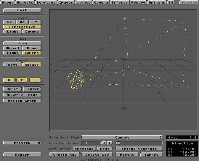
On entering the Layout environment, the large window provides you with a panoramic view of the 3D universe in which LightWave Scenes are created. Laid out before you is a horizontal Grid bearing a +Z and -Z notation on the back and front edges. This Grid is a reference plane which guides you when positioning Objects, Lights, etc. in LightWave's universe. It is helpful to think of this area as a film set, which extends infinitely in all directions, including up and down. The visible Grid is simply the XZ plane of the X, Y, Z coordinate system. To the left of the Grid's centre point is the -X direction. To the right is +X. The Y axis (up and down) is omitted from the view to minimise clutter. In the centre of the Grid, you'll see a small rectangular object. This is the Camera, through which LightWave 'sees' the worlds you will create. Initially, the Camera looks backwards along the Z axis of the Grid, so you are seeing it from behind. That's why it doesn't look much like a camera when you first see it. We'll soon fix that, when you learn how to control everything you see. In the graphic above, the Camera has been rotated to the right. Using Layout's tools and commands, you are the film director, controlling the 'actors', their surface appearance, their interactions and movement. You will also control the camera, lighting, scenery and special effects. You'll create things you never imagined!
The row of buttons across the top of the interface control the resources you will employ to produce the desired result, three-dimensional, rendered images. These buttons are Layout's Menus and are described in detail later. The separate button at upper right of the screen is labelled Modeler. Click on this to switch to the Modeler interface. When you do so, Layout will still be available through an analogous button on the Modeler screen. You can switch and interact between Layout and Modeler, thanks to the Amiga's multitasking capabilities. The button groups down the left of the screen will be described first.
Quit is self-explanatory, but when you exit LightWave after a Scene arranging or rendering session, various parameters are saved to the hard drive and are recalled the next time you Load that particular Scene. After clicking on the Quit button, you are returned to Workbench. The groups of buttons below the Quit button are inter-related. Mouse manipulation of items in the Scene is controlled by the combined settings of buttons in View, Edit and Mouse groups. The options available in the Mouse group alter according to the type of item selected under the Edit group.
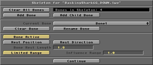
This panel pops up when you click the Object Skeleton button on the Objects Editor. It is used for adding and defining the properties of Bones. These are manipulated into an Object Skeleton using the Layout controls.
Following is a description of all the buttons and fields on the Skeleton control panel. Tutorial 5 provides a practical and detailed insight to the implementation of Bones in an animation project.
Click this button to remove all the Bones assigned to the Current Object. Note that Bones are not saved as discrete items, but form part of the Scene file. Also note that the Clear all Bones command is irreversible. Therefore, any mistake using Clear All Bones will require a complete re-Load of the Scene or a re-work of the Skeleton. The Scene file held in the 3D:Scenes directory, which contains all Bones data for the Object's Skeleton, remains unaffected. Only if the Current Scene is saved will the Bones data be updated to the hard drive. A query panel will ask for confirmation before you click Yes to complete the action.
Click this button to Add a Bone to the Current Object. On doing so, the Current Bone scroll bar will be filled with the default name 'Bone'. To help you with its use, each added Bone should be given a meaningful name using the Rename Bone button. All freshly added Bones are placed at the Origin of the Layout Grid. Relocate a new Bone to the desired position in the Object using Layout's Edit/Bone controls.
Add Child Bone will add a Child Bone to the Current Bone. The Current Bone name will change to 'Bone', the default name for all new Bones. Change this name as appropriate using the Rename Bone button. A Child Bone is added to the sharp end of the Parent Bone. In this way, chains of child Bones can be built up to form a backbone-like structure. The Parent of any Child Bone is the one it is connected to at its blunt end.
Located just above the Add Child Bone button, this displays the total number of Bones in the skeleton of the Current Object.
The Current Bone scroll bar contains the name of the currently selected Bone. To change the Current Bone, place the cursor on the bar and press the LMB. A pop-up list of all Bones within the Current Object will appear under the cursor. While holding down the LMB, move the cursor to the required Bone and release the LMB. The required Bone is now the Current Bone. Only the Current Bone is affected by the buttons in this and the lower section of the Skeleton panel.
Click this button to Clear the Current Bone from the Skeleton. Only the Bone held in RAM is removed, though there is no undo for this command. Mistakes using Clear Bone will require a complete re-Load of the Scene or a re-work of the Skeleton. The Scene file held in the 3D:Scenes directory, which contains all Bones data for the Object's Skeleton, remains unaffected. Only if the Current Scene is saved will the Bones data be updated to the hard drive.
Go back to the Home Page
Introduction
The Gallery
Downloads
WaveGuide Manual
Tutorials
My Amiga
Other LightWave Sites